|
Sludge Pumps
A pump capable of handling fluids with high solids content
Efficient • Economic •Dependable

All Holywell products are copyright or protected by patent application
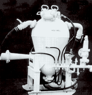
SLUDGE PUMP
The Sludge Pump consists of three sections as described below:
SUCTION SYSTEM
The suction system is operated by an Ejector Unit which should be supplied with compressed air at 55 p.s.i. Minimum (3.872 Kg/cm2) when 325 c.f.m. (554 m' per hour) will be consumed. The maximum allowable supply pressure is 75 p.s.i. and this pressure limit is controlled by a full flow relief valve.
When in operation, the Ejector Unit subjects the vessel to a high vacuum, thus allowing material to be collected via the flexible suction hose which is connected to the vessel top.
The suction hose is an abrasion resistant rubber approved for use underground and suitable for handling slurries. This hose has a bore size of 3" (76.2mm) and is normally supplied 20 feet long (6096mm). For industrial applications, where more abrasive materials may be handled, correspondingly suitable hoses can be supplied.
The collection end of the hose is fitted with a steel socket which is supplied with a secondary air supply from the machine distribution range which allows the suction end to be totally immersed. Secondary air requirements should normally be 150 to 200 c.f.m. (255 to 340 m3/hr.) maximum and this should be allowed for when selecting compressor capacity. When it is not necessary to immerse the suction socket, this line can be disconnected and secondary air will be freely induced from atmosphere into the system.
STORAGE VESSEL
The Storage Vessel is designed in accordance with BS 1500 Class III. Hemispherical ends are manufactured from carbon manganese steel and the conical body section from carbon steel. It has a nominal effective operational capacity of 60 gallons (273 litres).
DISCHARGE SYSTEM
Material discharge is from the bottom of the vessel via a 4 inch (100 mm) steel pipe bend-and ball valve. The machine is capable of delivering over a total distance of 200 metres (656 ft.) horizontally or 50 metres (164 ft.) vertically. To aerate the material and assist flow from the vessel, the discharge bend is fitted with an H.P. air connection, the flow from the vessel being implemented by the H.P. blow-down connection on the top of the vessel. The maching is fitted with instructions and air circuit plates which clearly describe the operating sequences.
SLUDGE PUMP
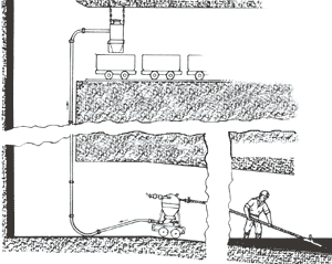
The drawing illustrates a typical application of the Sludge Pump where it is being used to clear an accumulation of flooding sludge.
Obviously, there are many varying situations in which the Sludge Pump can be employed in mining, tunnelling and civil engineering.

SLUDGE PUMP
PERFORMANCE (Typical)
Wet sludge ratio |
2 coal dust to 1 water |
| Minimum Air requirements |
554 m3 per hour at 3.872 Kg/cm2 |
| Minimum Air requirements |
325c.f.m. at 55 p.s.i. |
Minimum Air requirements
(totally immersed with secondary air) |
525 c.f.m. |
| Suction/Discharge Cycle Rate |
5 to 6 tonnes per hour |
| Unit Storage Capacity |
273 litres (60 gallons) |
| Lift |
200 m. horizontal or 50 m. vertically max |
MACHINE DIMENSIONS
| Height |
1670 mm |
(5'5 3/4") |
| Width |
1000 mm |
(3'3 3/8") |
| Length (no hose) |
1600 mm |
(5'3") |
| Machine weight (calculated) |
680 Kg |
(1500 lbs) |
| Suction line diameter |
76.2 mm |
(3") |
| Suction line length |
6096 mm |
(20 ft) |
| Air supply line connection |
1 1/2" B.S.P. |
|
| Air supply line length |
9144 mm |
(30 ft) |
Material Discharge Line
(Customer Supply) |
4" |
|
| 


